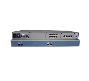
PCM Multi-service Optical Terminal (RS1030)

![]()
RS1030 is designed as a STM-1 level optical terminal with two 155.520Mb/s optical interfaces to provide an ultra-compact, cost-effective and flexible multi-service platform. It can realize the E1(up to 8E1), V.35, PCM traffic and 100Mbps Ethernet transmission over optical line.
RS1030 supports port-based VLAN and IEEE 802.1Q tag-based VLAN. By adopting ITU-T G.7041, G.7042 and G.707-compliant EOS (Ethernet Over SDH) technology and VLAN technology, each Ethernet port can employs 1~4 separate Virtual Concatenation Groups (VCG), and each VCG can be assigned to one or more Ethernet ports. The bandwidth of VCG can be flexibly configured for efficient transmission of Ethernet data over SDH network.
RS1030 supports NE management based on CLI command and RayView network management platform based on SNMP_V1 and SNMP_V2 protocol, to perform excellent management such as configurations, alarm monitoring and performance statistic.
RS1030 is suitable for data access network on the client side. With the technology compliant to ITU-T standards, it can communicate with products from other vendors adopting the same standards.
Feature
- Standard rack with 1U height and 19 Inch width
- Cross-connection with TU-12 granularity
- Optical Interface
- Two STM-1 interfaces, LC type SFP module , hot pluggable
- Complies with GB/T15941-1995 and ITU-T G.813 standards
- Supports RPD (Remote Power down Detection) information sending function
- Supports ALS (Automatic Laser Shutdown) to protect operators from hurt
- One card slot for 4 / 8E1 card or 2E1+V.35 card or 8E1+8PCM / 16PCM card
- E1 Interface
- Up to 8E1
- Optional 120Ω balanced E1 interface / 75Ω unbalanced E1 interface
- E1 interface complies with ITU-T G.703 standard
- V.35 Interface
- DB25 connector, complies with ITU-T V.35 standard
- V.35 interface supports non-framed and framed mode, the bit rate is N×64Kbps(N=1~31)in framed mode and 2048Kbps in non-framed mode
- In framed mode, the PCM30/PCM31/PCM30C/PCM31C mode is optional
- Supports DCE and DTE mode, in DCE mode, the master timing and tracing timing is optional; while in DTE mode, it only supports tracing V.35 timing
- Supports phase settings between V.35 output data and clock
- Supports link fault pass through function, which can notify V.35 port that the E1 side is failed
- PCM interface
- Up to 16 FXO / FXS / magneto interfaces
- Up to 8 2/4-wire E&M audio interfaces
- Up to 8 64K data/ RS232 /RS485 data
- Ethernet Interface
- Four LAN ports(physical port), each LAN port supports auto-negotiation, it can also be set to 10M full/half-duplex, 100M full/half-duplex mode by force
- Four WAN ports (internal port and invisible), each WAN port employs a VCG; the total bandwidth of 4VCGs is 63 VC12 and the bandwidth of optional one VCG is up to 48 VC12(100Mbps)
- The LAN and WAN ports are compatible with IEEE802.3/802.3u standard
- Supports flow control and broadcast storm filtering control
- Supports port-based VLAN and IEEE802.1Q tag-based VLAN
- Supports GFP-F Encapsulation specification complying with ITU-T G.7041
- Supports VCAT specification complying with ITU-T G.707
- Supports LCAS specification complying with ITU-T G.7042
- Provides both LCAS and Non-LCAS modes
- The maximum tolerated differential delay between any two VC-12 channels is 112ms
- SDH equipment timing mode
- ITU-T G.813 internal oscillator
- STM-1 line timing (T11,T12)
- The timing source can be operated automatically or controlled.
- Protection
- Supports 1+1 path protection with switching time less than 50ms
- Supports Automatic protection mode and manual protection mode
- Supports embedded BERT and various loop back for troubleshooting
- Supports FTP protocol and firmware download online without disturbance of existing traffic
- NE Management
- Provides serial management interface(CONSOLE) and Ethernet management interface (EMU), both adopt RJ45 connector
- Supports network management based on SDH overhead or on internal E1 channel
- Supports NE management based on CLI command via RS232 interface or TELNET
- Supports RayView network management platform based on SNMP_V1 and SNMP_V2 protocol to perform excellent management
- Supports hot-spare power, the power consumption is less than 15W /25W
- -48V DC single power access
- -48V DC double power access
- 220V AC single power access
220V AC double power access
-48V DC+220V AC double power access
PCM sub-module list
|
Model |
Name |
Description |
|
PCM-4FXS
|
Foreign exchange station module |
Provides a 4ch FXS interface, connects to user phone directly. Works with PCM-4FXO module to achieve extension of PBX user line |
|
PCM-4FXO
|
Foreign exchange office module |
Provides a 4ch FXO interface, connects to PBX user interface. Works with PCM-4FXS module to achieve extension of PBX user line. |
|
PCM-4MAG |
magneto telephone module |
Provides a 4ch magneto telephone interface, adopts 2100Hz inband signaling with signaling transmission and detection function, mainly apply to order wire, private line etc,. Occasions. |
|
PCM-2EM-2/4 |
2/4 wire E&M audio module |
Provides 2ch 2/4 wire E&M audio without signaling, supports 2/4 Wire mode online switch. |
|
PCM-2RS232
|
RS232 Interface module |
Provides a 2ch RS232 asynchronous interface, each channel occupies one 64K time slot. Supports rate from 0Kbps~19.2Kbps. |
|
PCM-2RS485
|
RS485 interface moudle |
Provides a 2ch RS485 asynchronism interface, each channel occupies one 64K time slot. Supports rate from 0Kbps~19.2Kbps, half-duplex mode. |
|
PCM-2CD64K |
64K data module |
Provides a 2ch 64K data interface, complies with ITU-T G.703 |
Application

Figure 1 Point to point network
![]()
Figure 2 Chain network
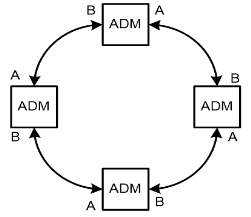
Figure 3 Ring network
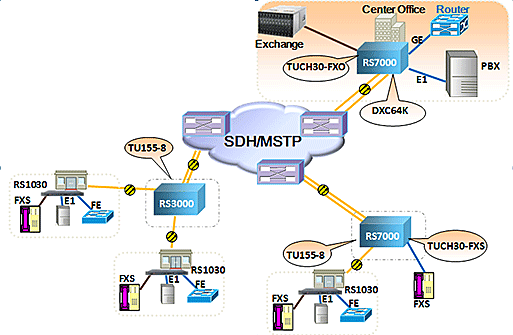
Figure 4 PCM application
Note: Make sure optical A of one NE must be connected with optical B of its neighboring NE.
